Last updated on May 24th, 2016
Those who are involved with technical practice related to micro controllers like Arduino, Raspberry Pi, etc…must be knowing that these devices need a DC regulated power supply. These units have their own DC Voltage regulator but they generate a lot of heat. Let’s say, Arduino Uno has a limit of 6V to 20V DC in. If you are powering up these devices with less than 9V & 1A, there won’t be much heat loss. But when the input voltage is raised above 9 volts there is significant heat generation on the board which requires your concern if you are seeking to use it for a longer period.
 Regarding this, why take a risk? Be on the safe side! So now, there comes a need to have a regulated power supply. It’s time to unleash the engineer inside you. Here’s a number of easy steps which you’ll find helpful while designing your own regulated power supply. Also, if you have a USB power bank it will do the job. Just connect it via the cable you use to program the device.
Things you will need
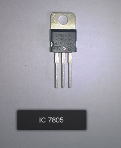
- 7805 Voltage Regulator
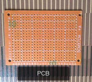
- PCB (Prototyping Board)
- Wires(of different colours)
- 2-Pin Connectors (2pcs)
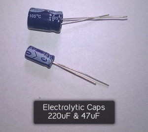
- Capacitor
Electrolytic: one 220uF and one 47uF
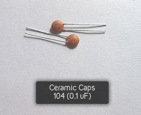
Ceramic: 104 (0.1uF) – 2 Pcs - LED (Any colored 3mm or 5mm)
- Power Supply Jack
- Soldering Equipment
- Resistor: 1K – one piece
- Diode (5400)
- Heat Sink
- Battery: 6V, 9V or 12V
Working:
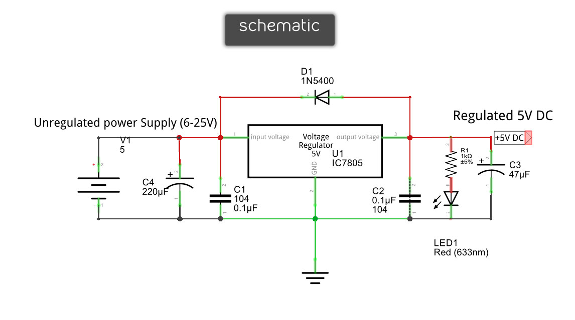
IC 7805 is a DC Voltage regulator which maintains the potential difference of 5 volts to the output with a max of 1.5 A to 2.0 A depending on the manufacturer. The input voltage can vary from 6V to 25 V DC. So, you can connect any battery to the input but that should be giving more than 6 volts.
Ceramic Capacitors to the input and output terminals are for removing any spike of voltage i.e, to remove oscillation of the voltage in the circuit. Even without the ceramic capacitors the circuit will work. But when you’ll be powering up the radio, Bluetooth or Wi-Fi Module using this circuit, there will be a lot of unwanted noises. Therefore, a pair of ceramic caps will eliminate the noise to make your circuit more versatile.
The electrolytic capacitors are used for smooth and steady DC operation i.e, to remove any significant noise to the input as well to the output. Also, it prevents your load and IC both from the instantaneous surge.
The Diode IN5400 is a reverse protection diode in this circuit which prevents the regulator IC from discharging surge of the Electrolytic Capacitors. The Heat-Sink connected with the regulator is a must, as it prevents the regulator IC from overheating.
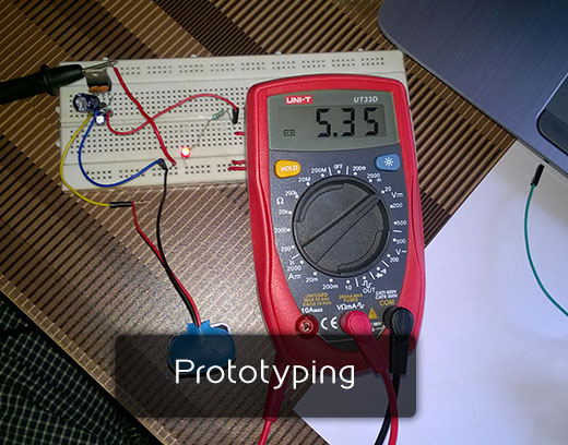
Use a good quality PCB to first prototype the circuit. If you find yourself in any trouble, comment below. Well, the circuit is tested several times. It works well enough. Take proper care of the terminals and add an LED to the output. Don’t forget to add 1K Ohm resistor with the LED.
Solder the components as per the schematic and double check for any error. Now, you have made your own Power supply for Arduino.